Table of Contents
Introduction
Currently, I’m learning about the C4 model which I’m evaluating to determine its usefulness for future projects. It is used to model software architecture. According to the license, I may use the images from the website. The images used in this post are from Simon Brown, from https://c4model.com/ (CC BY 4.0).
The C4 Model defines four abstractions:
- Software System
- Containers
- Components
- Code
Each diagram has certain “boxes” on them, and each box can be zoomed in on to get an overview of the next level in the hierarchy of the models. The following image is from the c4model.com website:
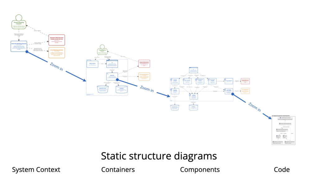
So far, I get strongly reminded by how IDEF0 works, which is used to model functions, decisions and activities of an organization or system. It also uses a hierarchical depiction in the same fashion.
The Goal of the Model
According to the website the C4 Model aims to raise the maturity associated with software architecture diagrams. To better (visually) communicate with all stakeholders of a software development project.
The four Levels of Abstraction
This is a synopsis of the standard terminology. According to the documentation, custom terminology may be chosen. If you choose certain terminology, then stick with it for consistency.
Software System
On the highest level of abstraction there is the Software System. It is something that delivers value, in its most abstract sense. It is the overall product, application, service or any other term you can use for what was built to deliver value to customers or the business.
The Container
Anything that is needed to run the Software System. Examples are a database, the Angular framework, a shell script, a file system, a client-side desktop application, a web app, etc.
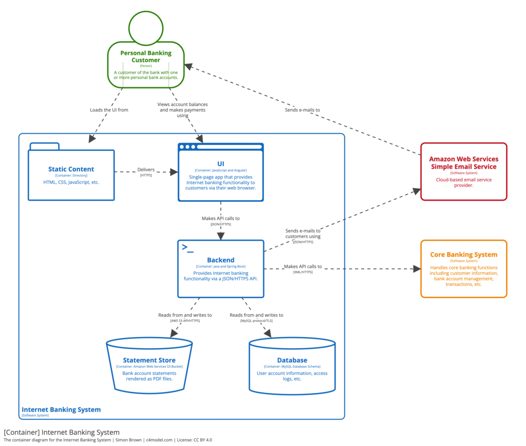
The example component diagram about a Web Application used components such as: Static Content, UI, Backend, Database, Statement Store, which we’ll see further down.
Component
A grouping of related functionality encapsulated behind a well-defined interface. Or stated differently, in terms of Java or C#: a collection of implementation classes behind an interface. In other terms a component can be described as a runtime boundary around code that is being executed or data that is being persisted.
Code
Diagrams about the code. The website describes a Dynamic Diagram and a Deployment Diagram, but UML can be used as well.
Abstraction Levels Overview
| Level | Purpose | Key Elements |
|---|---|---|
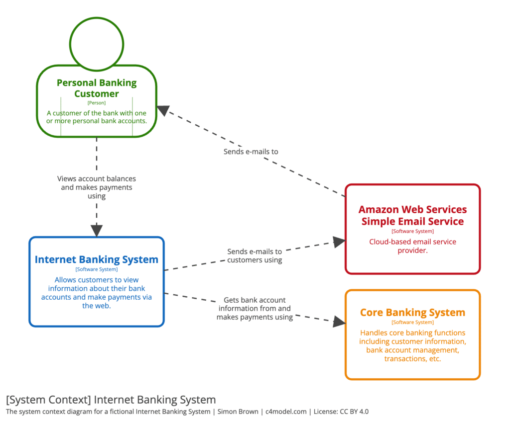
| System Context | Show scope and external actors, overall IT environment | System box, external nodes |
| Container | High level shape of software architecture | e.g. UI, backend, API service, database |
| Component | Responsibilities and technology/implementation details | Interfaces, modules |
| Code | Code level structure and relationships | Classes, packages, sequences |
The System Context diagram will fit inside a so-called System Landscape Diagram. This diagram further widens the context of the System.
What was not immediately clear to me was that a Container diagram does not depict a container, but each box inside of the diagram is a container.
Each Component in the Component diagram groups together a number of classes and interfaces which implement a specific piece of functionality.
Diagram Examples
(From the c4model.com website)
System Context:
Container Diagram:
The container diagram zooms in on the Internet Banking System from the System Context diagram.
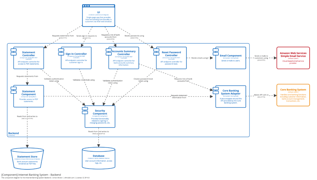
Component Diagram:
This example zooms in on the UI box from Container diagram. The other boxes should have sub-diagrams as well.
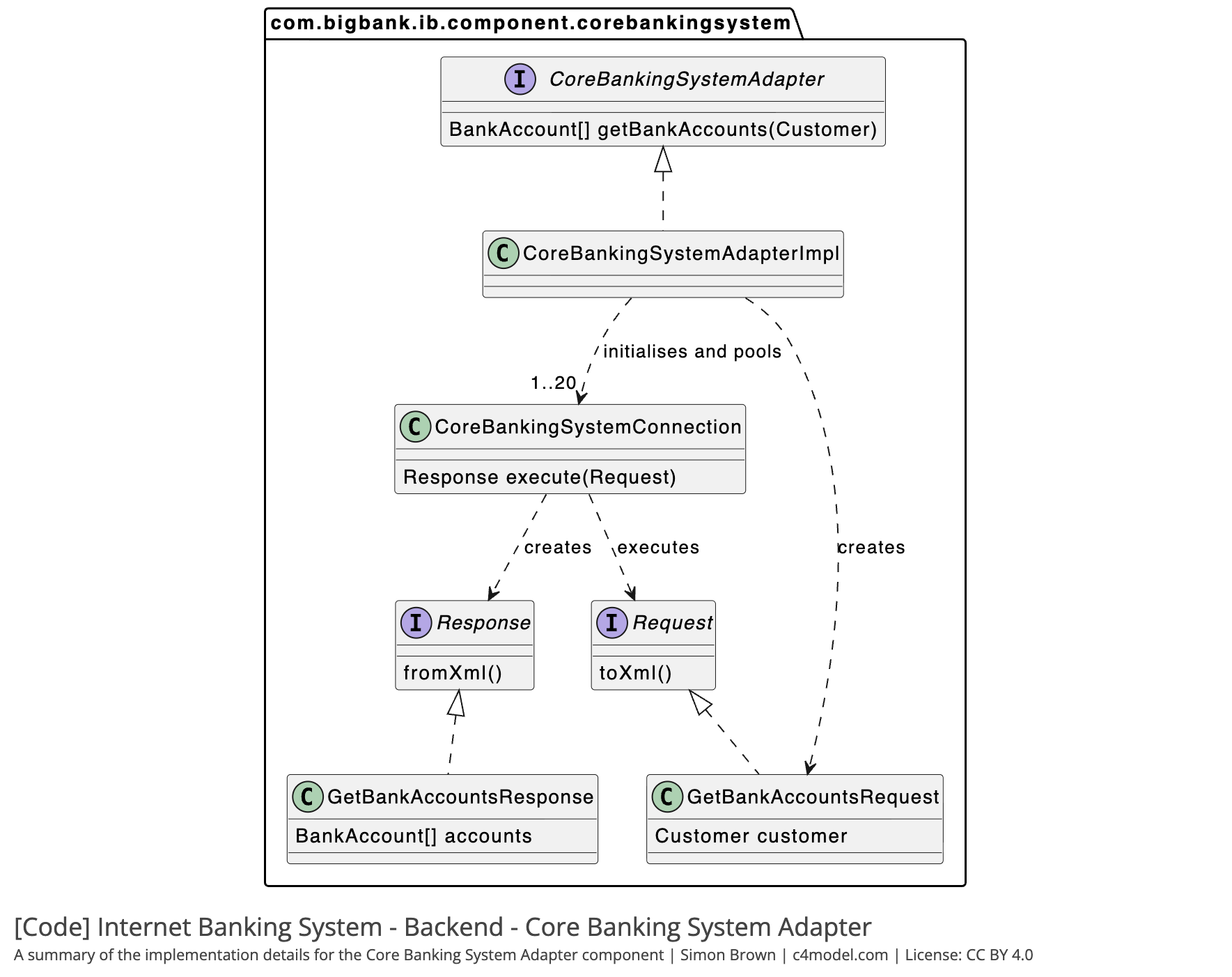
Code Diagram:
Each component can be made into one or more UML Diagrams. Such as a Class Diagram.
Tooling
There are several opportunities of tools available to aid in the development of the models/diagrams. C4 distinguishes in modeling versus diagramming in the following way: Diagramming is drawing the boxes and lines, where Modeling is creating a queryable dataset which is non-visual.
Conclusion
The C4 Model seems to fill a gap that standard UML does not fill: A clear consistent hierarchy. On the Code level of the hierarchy, it is advised to use UML diagrams. These could be class diagrams, sequence diagrams or other behavioral diagrams or a combination of them.