Table of Contents
Introduction
The official BPMN website emphasizes that BPMN serves as a graphical tool to facilitate communication about business processes among stakeholders from diverse backgrounds. At the time of writing, BPMN is in version 2.x. This post aims to provide a brief introduction on how to read and use BPMN effectively.
Basic Symbol Overview
Keep in mind that there sometimes exist other ways to express the same functionality with a slightly different notation in the diagram.
Events

A circle means an Event. The left circle is a Start Event (ignore the clock inside), middle is an Intermediate Event (double lines), and the right one is an End Event (thicker).
Each circle can have a symbol inside which further elaborates the meaning of the event (like: Timer, Signal, Message, etc). For instance, a clock symbol inside stands for a Timer Event. Each diagram starts with a Start Event. An Event can be interpretated as something that happens. For instance, when a customer places an order, that can be the Start Event for the rest of the process.
Activity

A rectangle with rounded corners represents an Activity. An Activity can be a Task, Subprocess, Transaction and more. (Also see the BPMN quick guide)
Above you see three examples of Tasks. Without a symbol, you read it as an Abstract Task. An image with a human on it represents a User Task, while the cogs represent a Service Task or Automated Task (by a computing entity). A Task is an atomic piece of work that has to be done as part of the process.
A Task with a thicker border (not shown here) is called a Call Activity, which is a reusable subprocess. This gives you the opportunity to call this process from multiple places in your diagram, without cluttering the original diagram with the entire display of this subprocess. For instance, a quality control check gets called multiple times in different stages of a production process. The details of the quality control check process can be defined in a different (sub)diagram.
Gateway

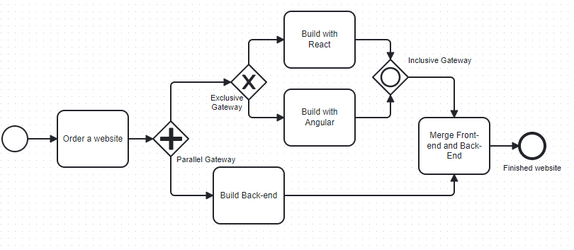
The five images above are different types of Gateways. These are basically connectors in the flow of the diagram, where paths can split or come together. From left to right:
- Exclusive Gateway (with X inside): The path can go several ways from this gateway, but only one of the paths can be taken at a time, hence the name exclusive. Compared to logic gates, this would be the same as XOR.
- Inclusive Gateway (circle): All paths from this gateway are evaluated simultaneously. All combinations of the path may be taken, from zero to all.
- Complex Gateway (*): This is the only gateway that has an internal state, which is a Boolean that is initially true. This gateway is used for more sophisticated decision making. There can be several lines going in the Complex Gateway. These inputs will be evaluated by the Complex Gateway. Based on the rules you defined; a certain combination of output lines will be activated.
- Event-based Gateway (pentagon): This gateway only uses one incoming event to determine the outgoing path or paths, in comparison to the complex gateway that uses all incoming inputs.
- Parallel Gateway (+): All outgoing flows will be executed simultaneously. If it has incoming paths, it waits for each input and synchronizes the process before moving forward. It uses no further conditions; it simply splits or joins the flow.

Sequence Flow

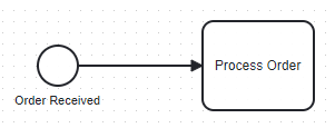
The line with the arrow represents the Sequence Flow. This is the order in which the process takes place. In the case of the image, a Start Event happened, that activated the Process Order activity. A Sequence flow cannot cross a pool boundary. Keep reading to find out about Pools.
Message Flow
Messages are represented with a dashed line instead of a solid one. They can only be used between Pools, which will be explained below.
Pool

A Pool represents a participant (e.g. a company, customer, manufacturer, etc) in a collaboration. Yes, this falls a bit from the sky, but in the official terminology a collaboration is a collection of participants.
A pool may or may not include processes. In the terminology, a process can either be private or public. A private process will be contained inside a single pool.
In the image there is a Customer pool and a Company pool, the big lanes surrounding the processes. Both these Pools together are called the Collaboration. In each Pool you can find a process, a flow from start event to end event. The Customer sends an order and waits until it is received. In the task Submit Order a message (dashed line) will be send to the Company.
At two points, the customer will receive a massage, from Process Order and from Dispatch Order. The white envelope represents a catch event, which purpose is to wait until the message is received. (A black envelope does also exist, and its purpose is to send a message).
Of course, there could be a technical issue at the end of the company where the mailserver throws an error and no confirmation or notification messages will be sent to the customer. You can choose to create a clause in the diagram that handles this issue. For this diagram, we just assume the customer will ultimately receive the order without notifications.
Artifacts
These can be Data Objects, Groups or Annotations. Artifact is used as the collective name.
- A Data Object can be either produced in an activity or is required for an activity.
- A Group is used to create a group out of different activities but does not affect the process or flow of the diagram.
- An Annotation gives extra information about anything on the diagram.
Association and Data Association
Associations give extra information and connect with artifacts. They are represented with a dotted line. An association can go a single direction (from A to B) or bidirectional (from A to B and from B to A at the same time). An arrow to a data object means that it saves data to the object, while an arrow coming from a data object means that it reads/retrieves data from it.

The group Order Activities is just to group together some activities to make it clearer. In this example there is of course only one activity, but it is just to show how a group is represented. You would usually add multiple activities inside a group.
The annotation is the text about the order processing, which in this case elaborates on what happens inside the activity.
From the Process Order activity (task) there will be data stored in a persistent database (Data Store), like order information. Maybe some temporare data, like the contents of a shopping cart will be stored in the Data Object.
Conclusion
We went through the basic building blocks of a BPMN diagram. There is a lot more to explore on the official bpmn.org website and on other sources. The diagrams in the examples are small and simple compared to what is usually modelled, just to create a solid baseline of understanding for the most common symbols/shapes.
References
Business Process Model and Notation – Wikipedia
BPMN Specification – Business Process Model and Notation (Specification PDF)
