Table of Contents
Part 5: Shelves
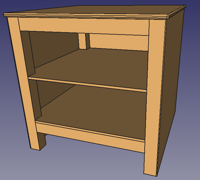
So far, this is just the basic design of the nightstand, there are no joints or connections modeled, nothing technical. Whether this is desirable for your project is up to you. For this project, I chose to model only a few parts to show how the beams are connected.
Drilling holes
We’re going to drill holes for shelf support. Find the Drill bit, drill simple holes button in the Woodworking workbench.

Select a face to place the drill bit on. We’ll select the insides of the legs of the nightstand. Create four of the drills bits, and place them as follows:
| Drill bit | X | Y | Z |
| 1 | 35 mm | 25 mm | 350 mm |
| 2 | 565 mm | 25 mm | 350 mm |
| 3 | 35 mm | 575 mm | 350 mm |
| 4 | 565 mm | 575 mm | 350 mm |
By double clicking on the drill bit in the tree view, you can alter its parameters, such as its radius and height. For now I leave it as it is.
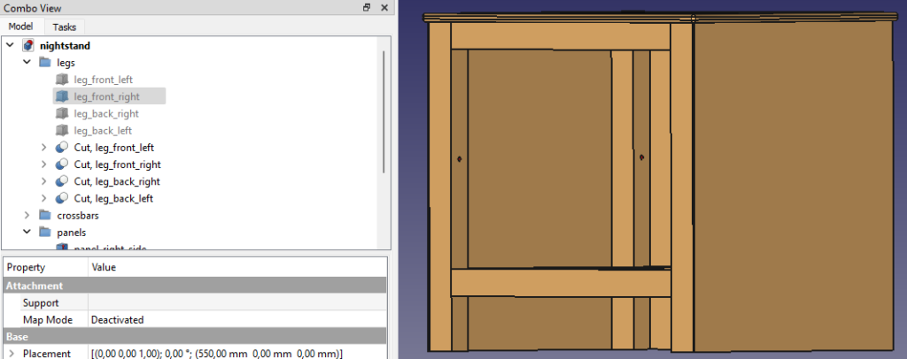
Select all four legs, and click the button cut dowels from panel.

This will hide the original leg and makes a cut object where both the leg and the dowel are in. The original leg objects are referenced from the cut objects, so they cannot be removed. The original drill bit objects can be removed because they are copied inside the cut object. Drag the cut leg objects inside the legs group in the tree view.
Shelves
In the woodworking workbench, create a new panel XY by pressing its button. In the Data tab of the Combo View, change its Length and Width to 600 mm both and the Height to 10 mm. Create a new group in the tree view and call it shelves. Rename the panel to a proper name and drag it to the shelf group. Now click on the Create body button with the new panel/shelf still selected.

Rename the body to something like shelf_body and also drag it inside the shelf group. This body has a BaseFeature inside, which references our panel we just created. We need this body type object for the things we want to do next.
Click on the shelf_body and set its z position via the Data tab in the Combo View to 600 mm so that it will become visible on top of everything else. Left click anywhere on an empty space in the 3D view to deselect all, and then click on the top face of the shelf_body. Now click on Create sketch. The sketcher workbench will automatically open itself.

The reason that we needed a so called body object, is that we can create a sketch on a face of the body and that we can add external geometry to align our sketches. This will hopefully become clear soon. If you’re new to FreeCAD and this remains unclear after just working with it, I would recommend to find other tutorials explaining more about this subject.
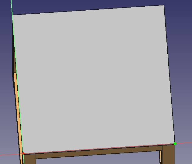
The Create external geometry button allows us to add vertices, edges and/or faces from outside our sketch to work with and to align our sketch with. Click on the Create external geometry button and add the bottom right vertex of our shelf/panel.

If the selection succeeded, the item 1-Point will be visible in the Elements area of the Tasks tab inside the Combo View.
Sketches
Click on the Create rectangle button and roughly draw four rectangles in the corners of the face. You can click on Top in the cube in the upper right corner of the 3D viewport to have the top view exactly.

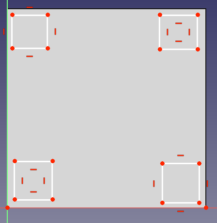
Now click on the lower right vertex of the lower right rectangle and control click on the externally added geometry vertex so both are selected.
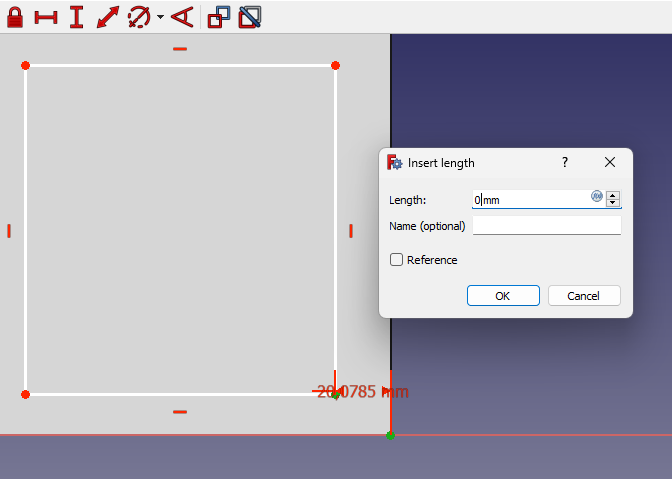
Constrain the first rectangle
Now click on the button constrain horizontal distance and enter 0 (zero).

Select the same two vertices again with control and do the same for constrain vertical distance, also with 0.
Now click to select only the top edge of your sketched rectangle, press on the constrain horizontal distance button (again), and enter 50. Click on the left edge and constrain the vertical distance also to 50 mm.
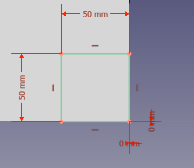
Zoom out far enough so you can see all four sketched rectangles. Deselect everything. Control left click on all four left edges of all four rectangles and press the Constrain equal button. The other three squares will now have the same constrained rules as the first one. Select all four top edges and press the Constrain equal button again. Now all our sketches have the same size.

Align the other rectangles
Now we have to align those other three rectangles on the shelf face perfectly as well. To do so, we’ll start with our top left rectangle sketch. Select the top left vertex (of the top left rectangle sketch) and select the bottom right vertex of our rectangle in the bottom right, which already is perfectly aligned. Click on the Constrain vertical distance button and enter 600 mm. Do the same (600 mm) for the Constrain horizontal distance, you will have to select the same two vertices again.
For the bottom left rectangle sketch, select the bottom left corner, while selecting the bottom right corner of the bottom right rectangle. Enter 600 mm for horizontal distance and 0 mm for the vertical distance. Now do the same for the top right rectangle using 0 mm for horizontal and 600 mm for vertical distance.
You should now have a fully constrained sketch. This should be visible in the Combo View Tasks tab. If not, retrace the previous steps. Now you can close the sketch and you will be returned to the woodworking workbench.

Cut out
Open the Part Design workbench. Select the newly created sketch in the tree view, which should be inside our shelf_body object. Click on the Pocket button and enter a length of at least the thickness of our shelf, which should be 10 mm.

Our shelf will now fit inside our nightstand.
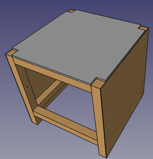
Click on the shelf_body in the tree view and give it a z position of 355 mm in the Data tab of the Combo view. We can now copy and paste the shelf and set the z position of the copied shelf to 150 mm.
